For the Week 8 group assignment, our objectives were:
Our lab performs in-house PCB fabrication using multiple CNC milling machines.
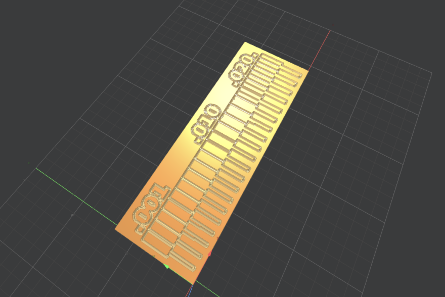
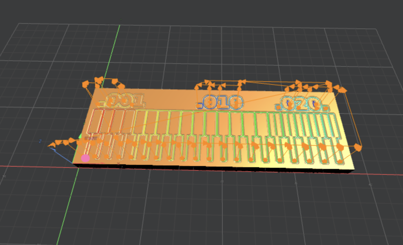
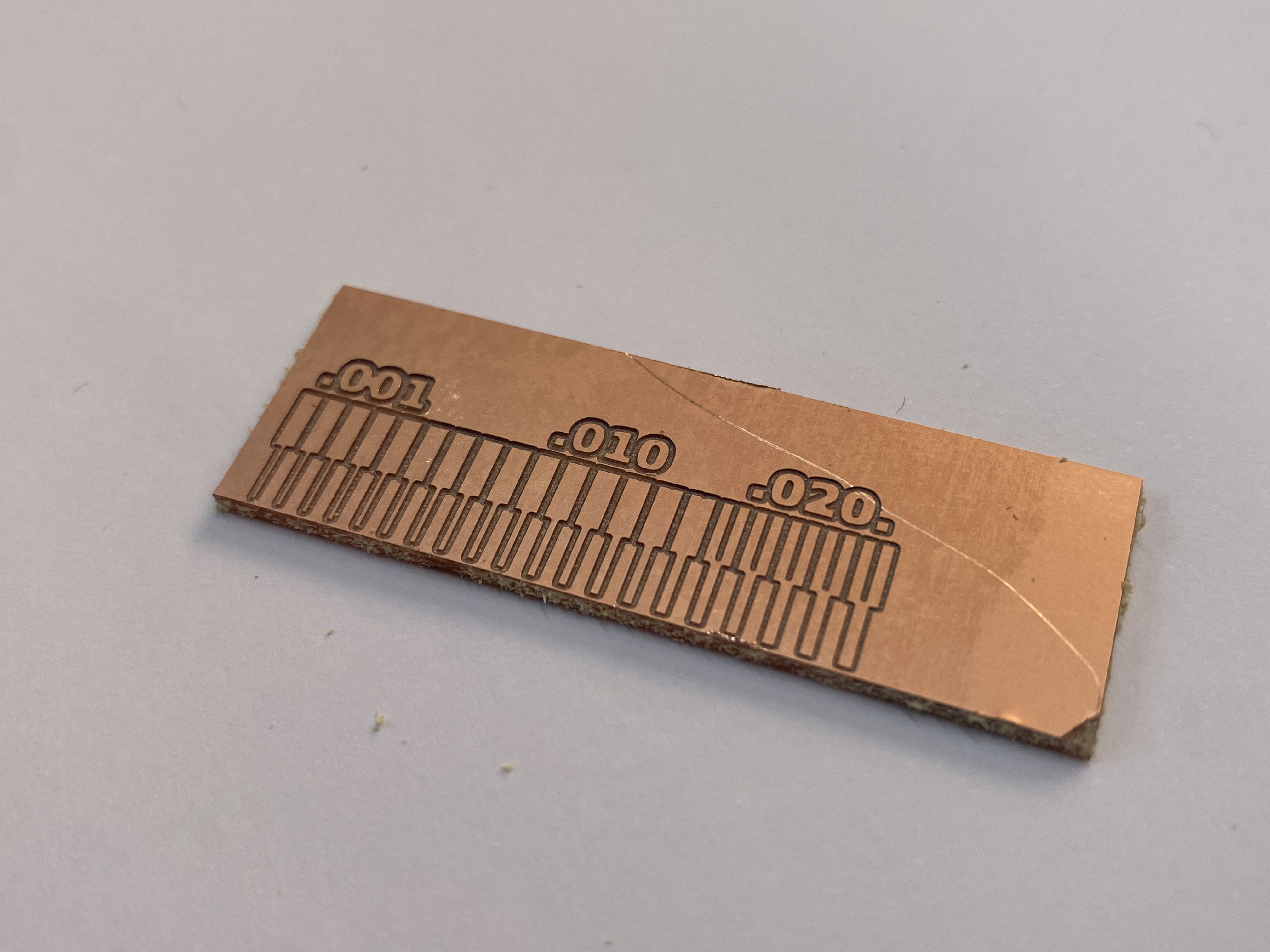
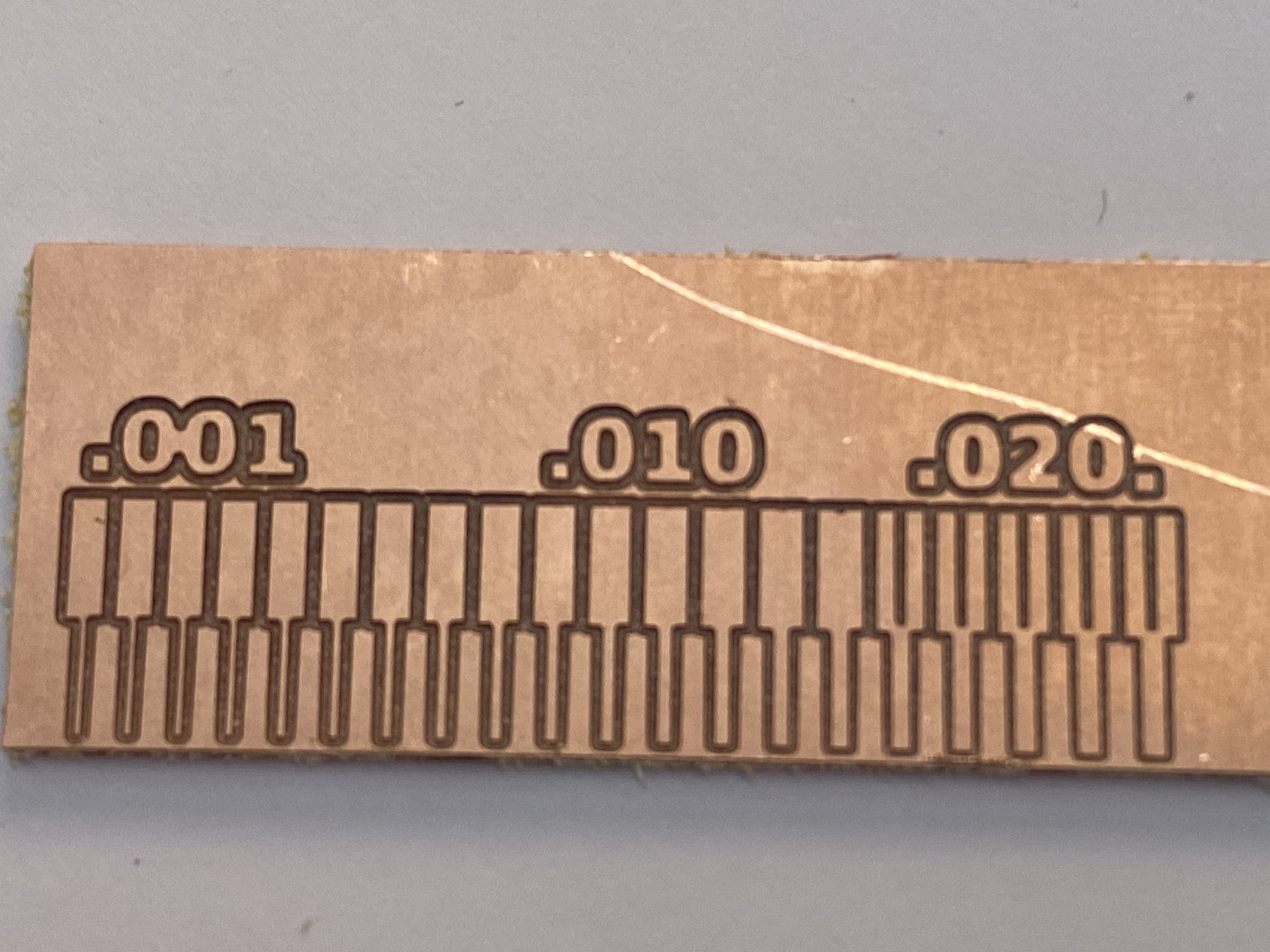
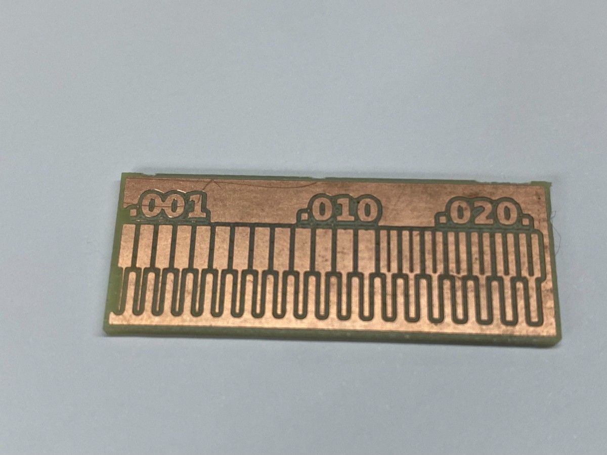
To determine the design rules of our process, we milled the Neil Gershenfeld PCB line test pattern, which contains traces with progressively smaller widths and spacing.
This allows us to determine:
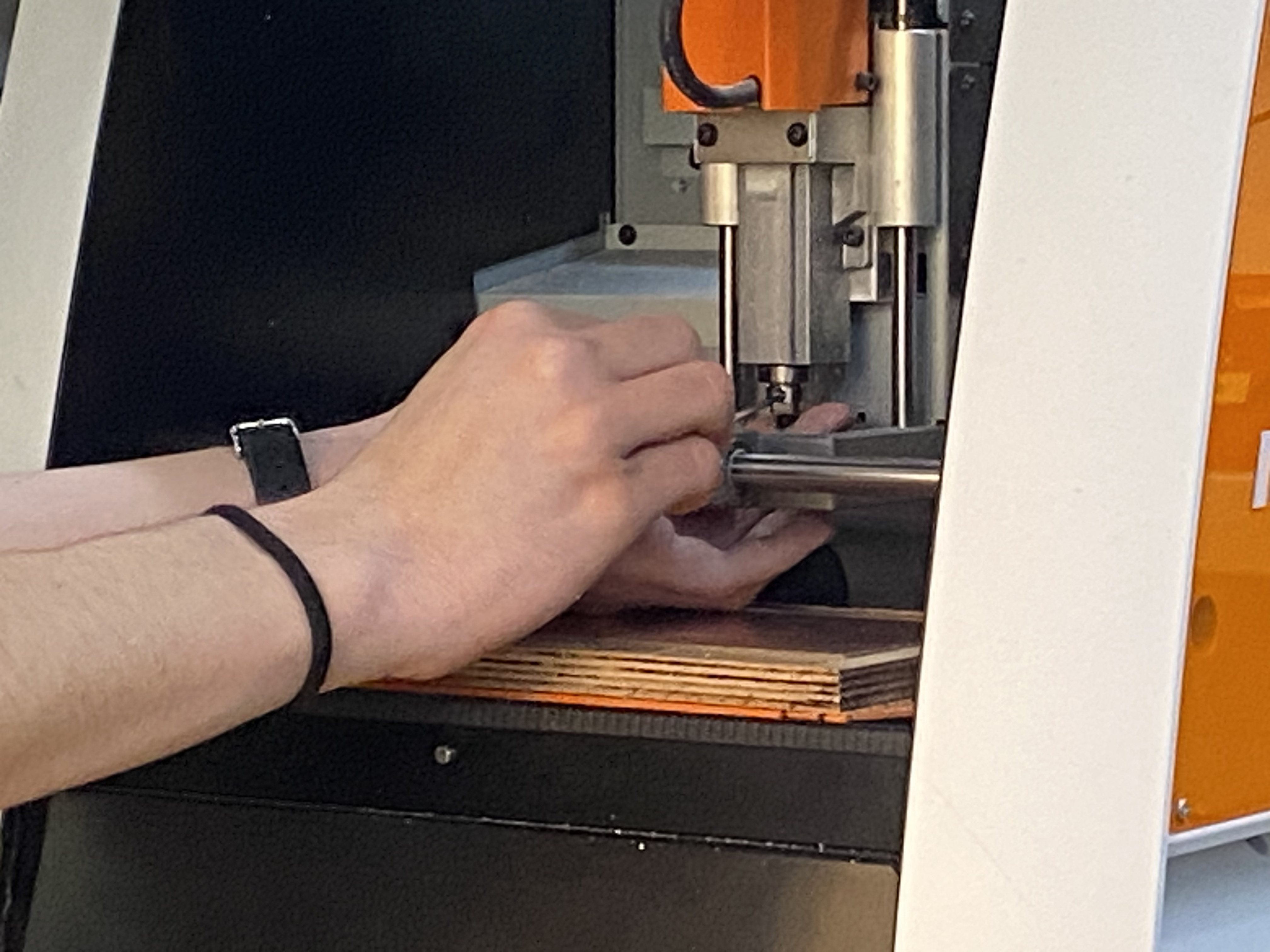
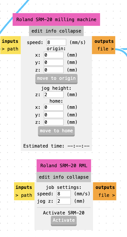
Our lab uses the Roland SRM-20 MonoFab for PCB milling.
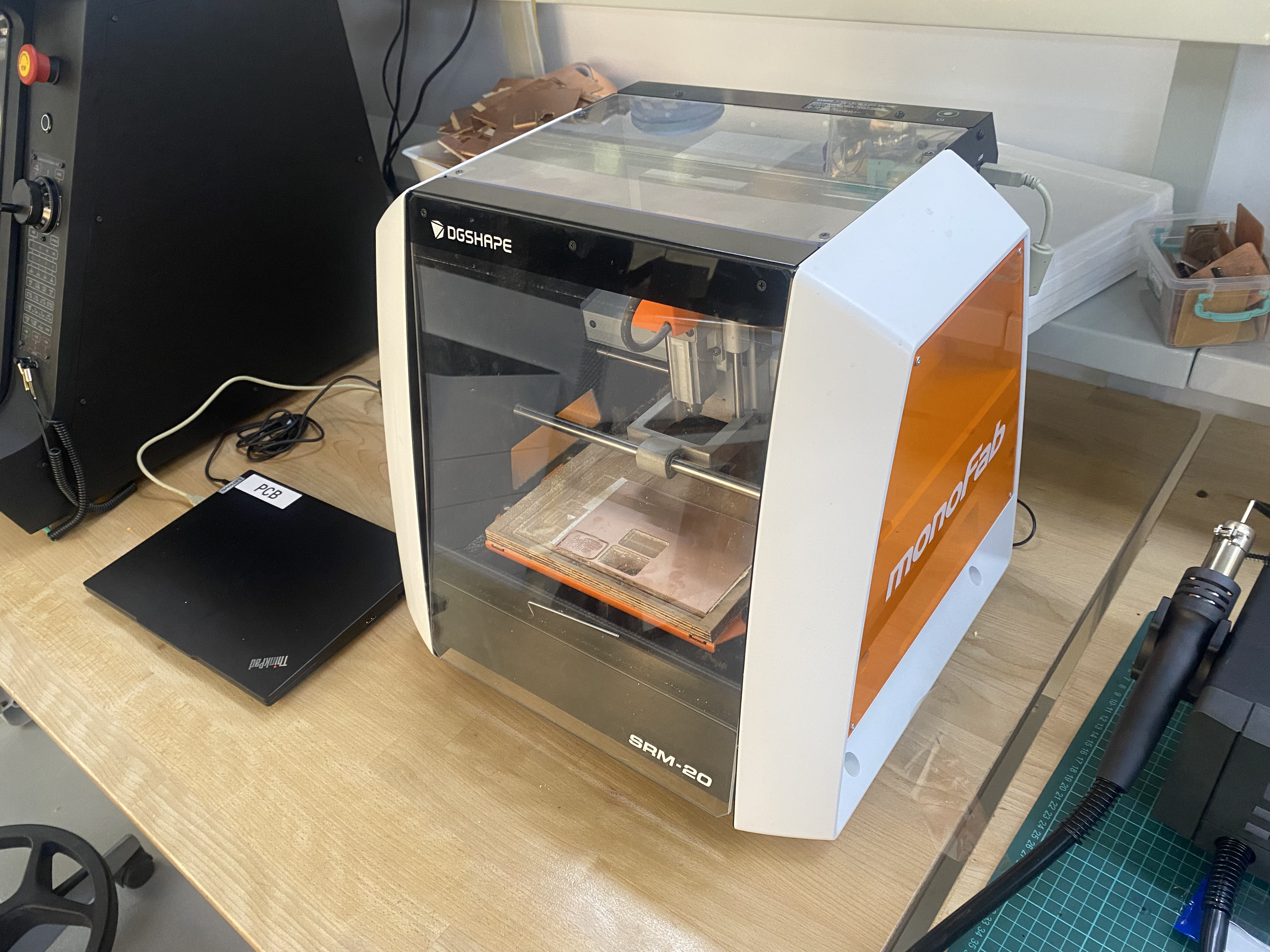
The machine mills copper from FR-1 copper clad boards using small milling bits to isolate electrical traces.
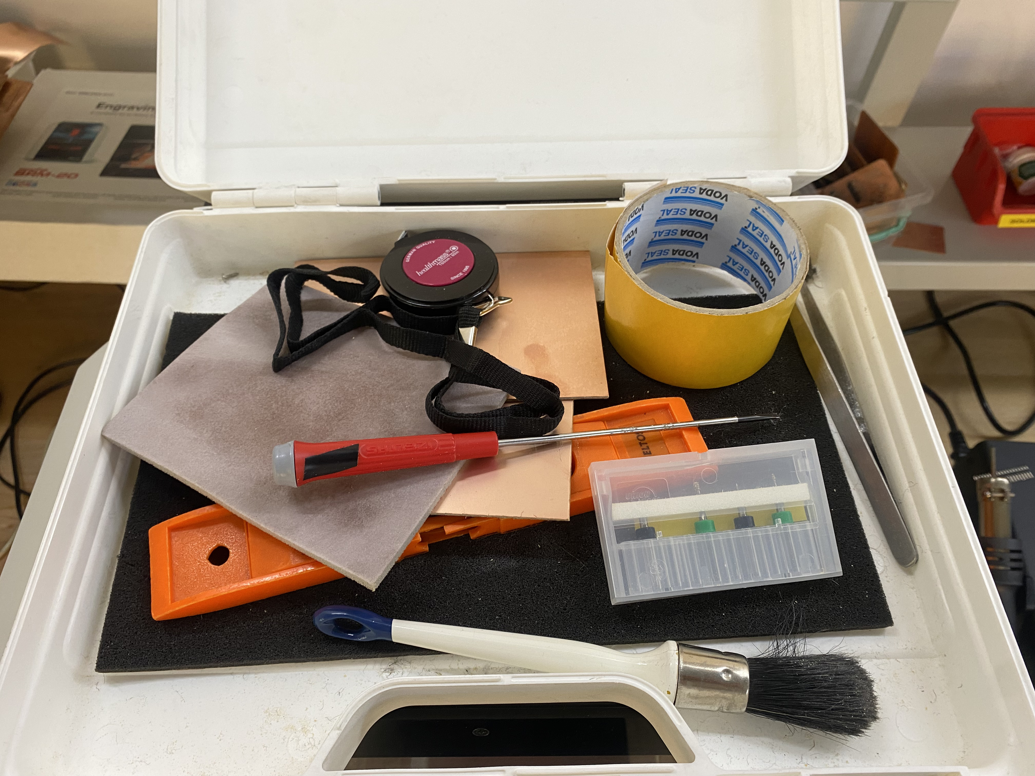
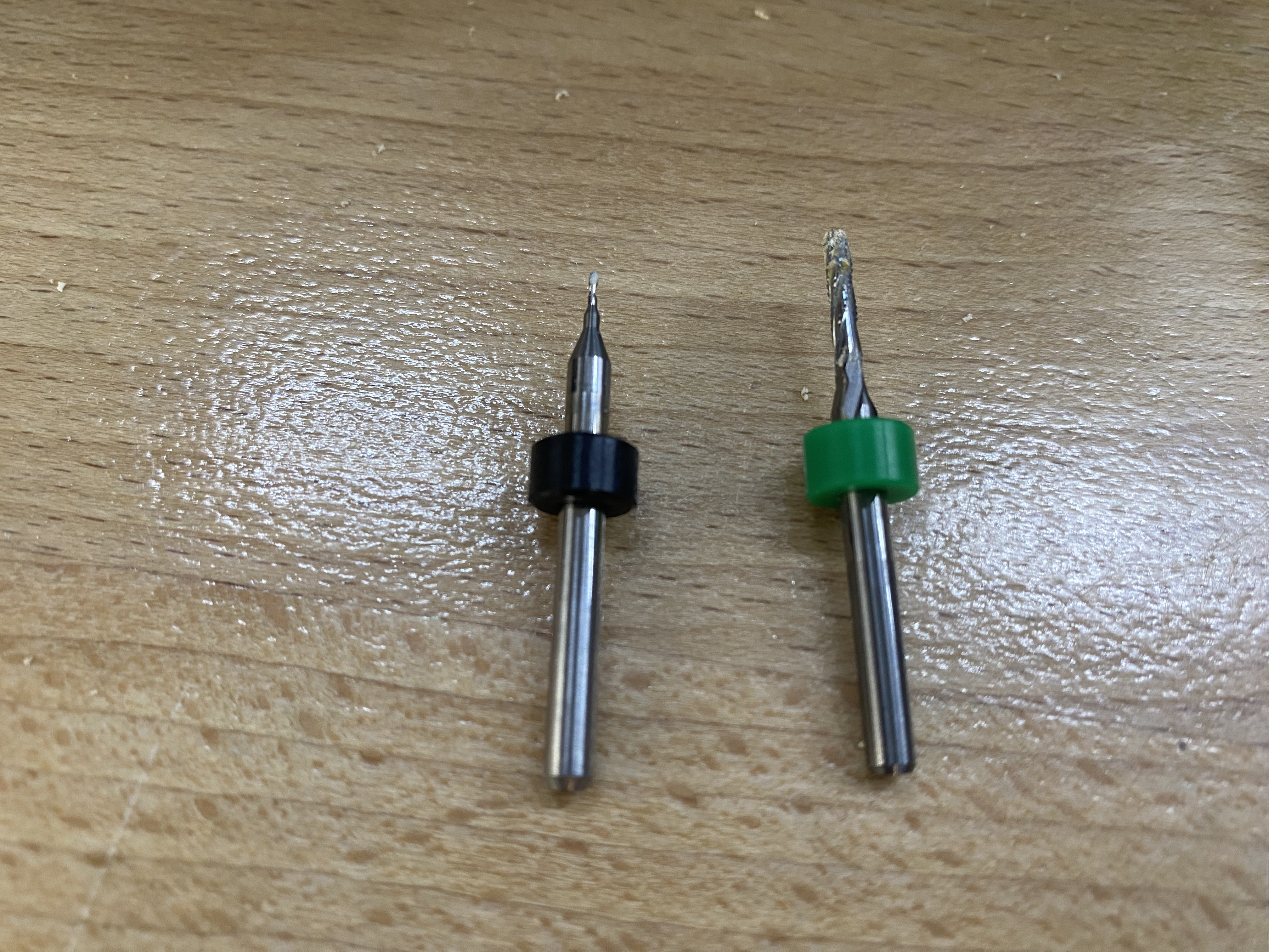
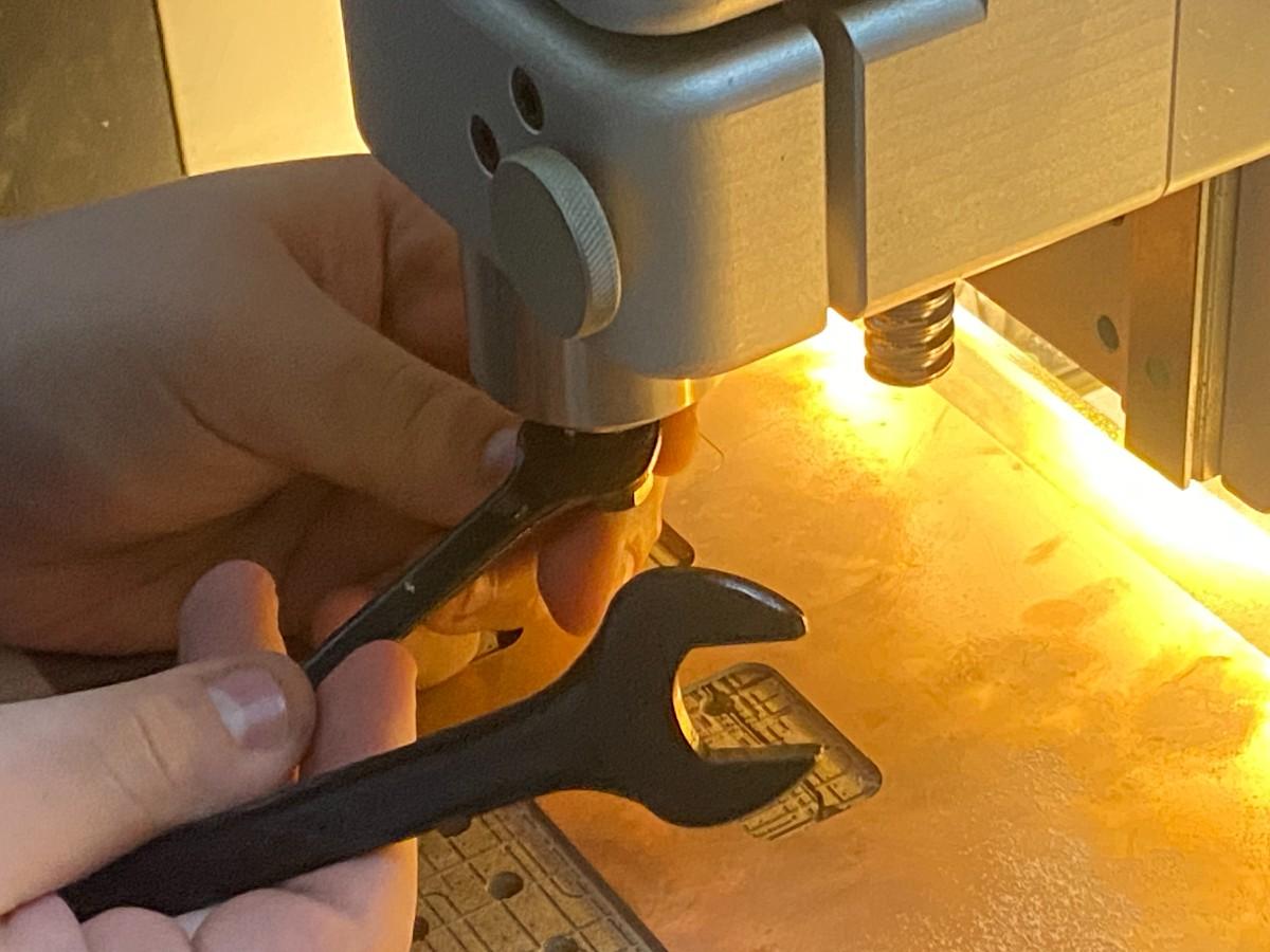
Before starting the milling process, we prepared the tools required for PCB production.
The toolkit includes:
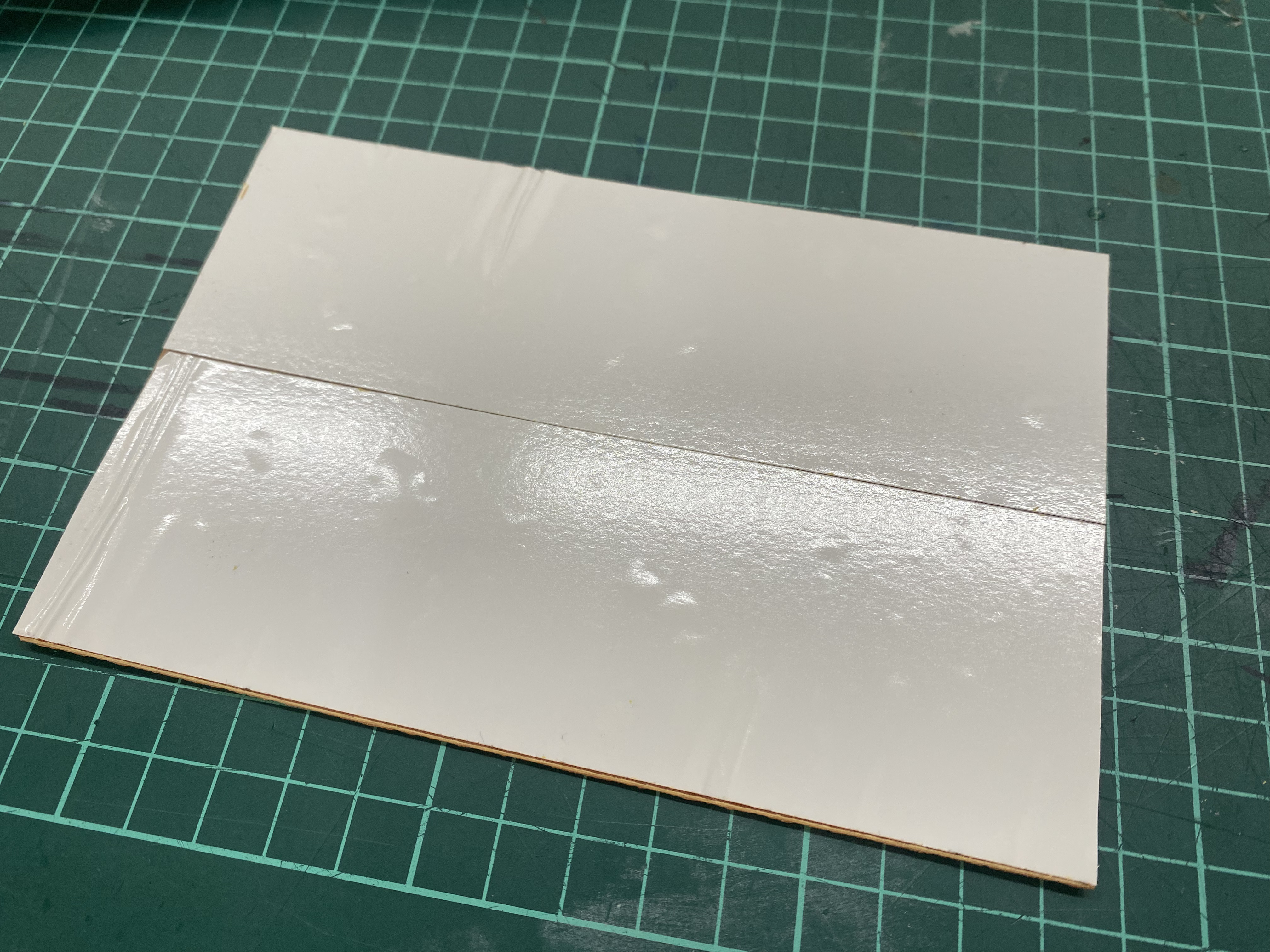
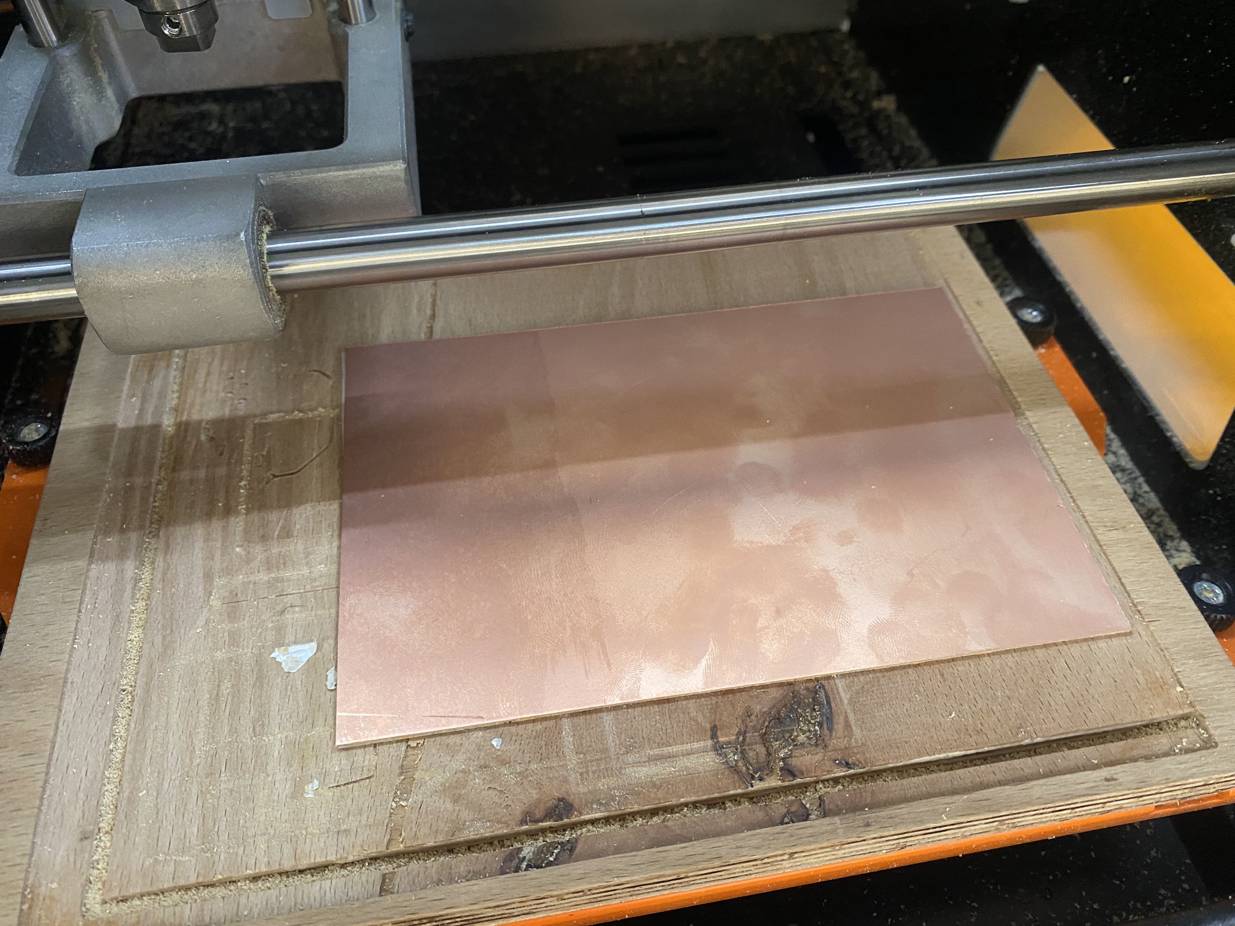
The PCB substrate used is a single-sided FR-1 copper clad board.
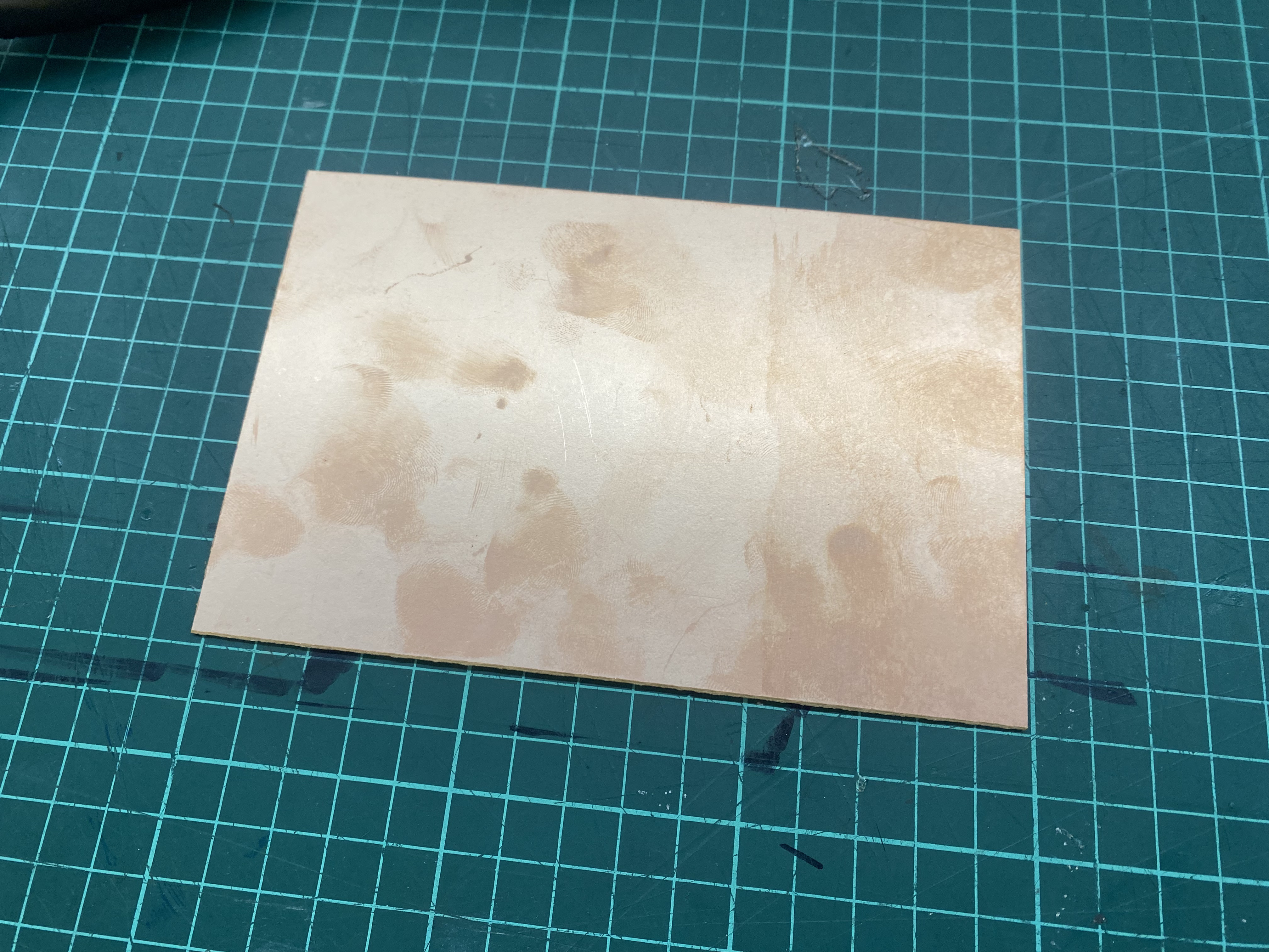
To attach the board to the milling bed, double sided tape is applied to the back.
The board is then firmly mounted on the machine bed.
Ensuring the board is perfectly flat is critical. Even small height variations can cause traces to fail during milling.
| Purpose | Bit Type |
|---|---|
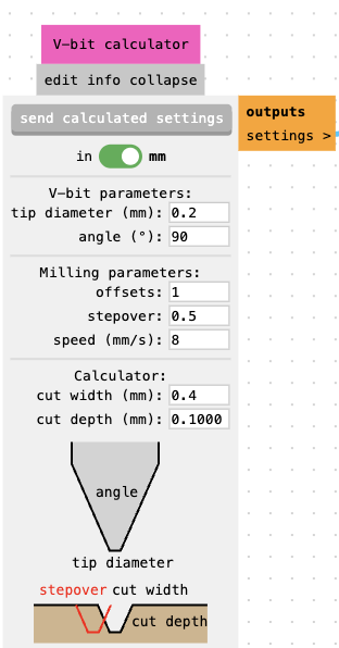
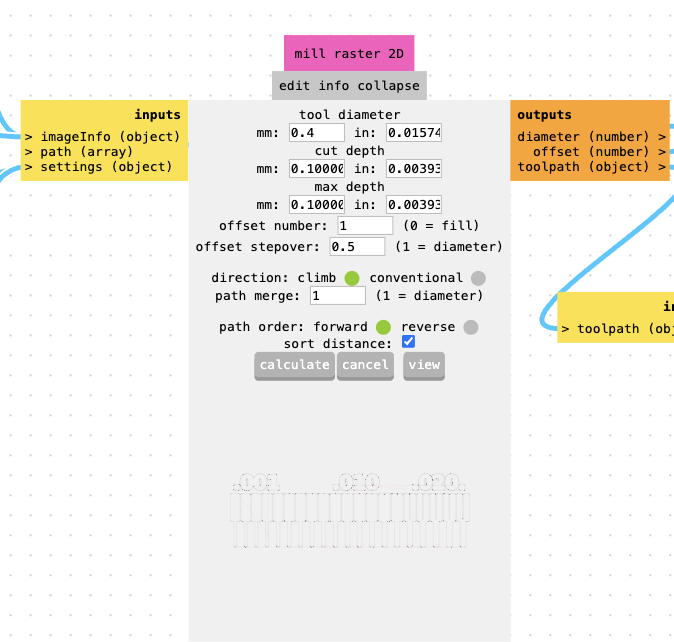
| Trace milling | 0.2 mm V-bit (90°) |
| Edge cutting | 2 mm flat end mill |
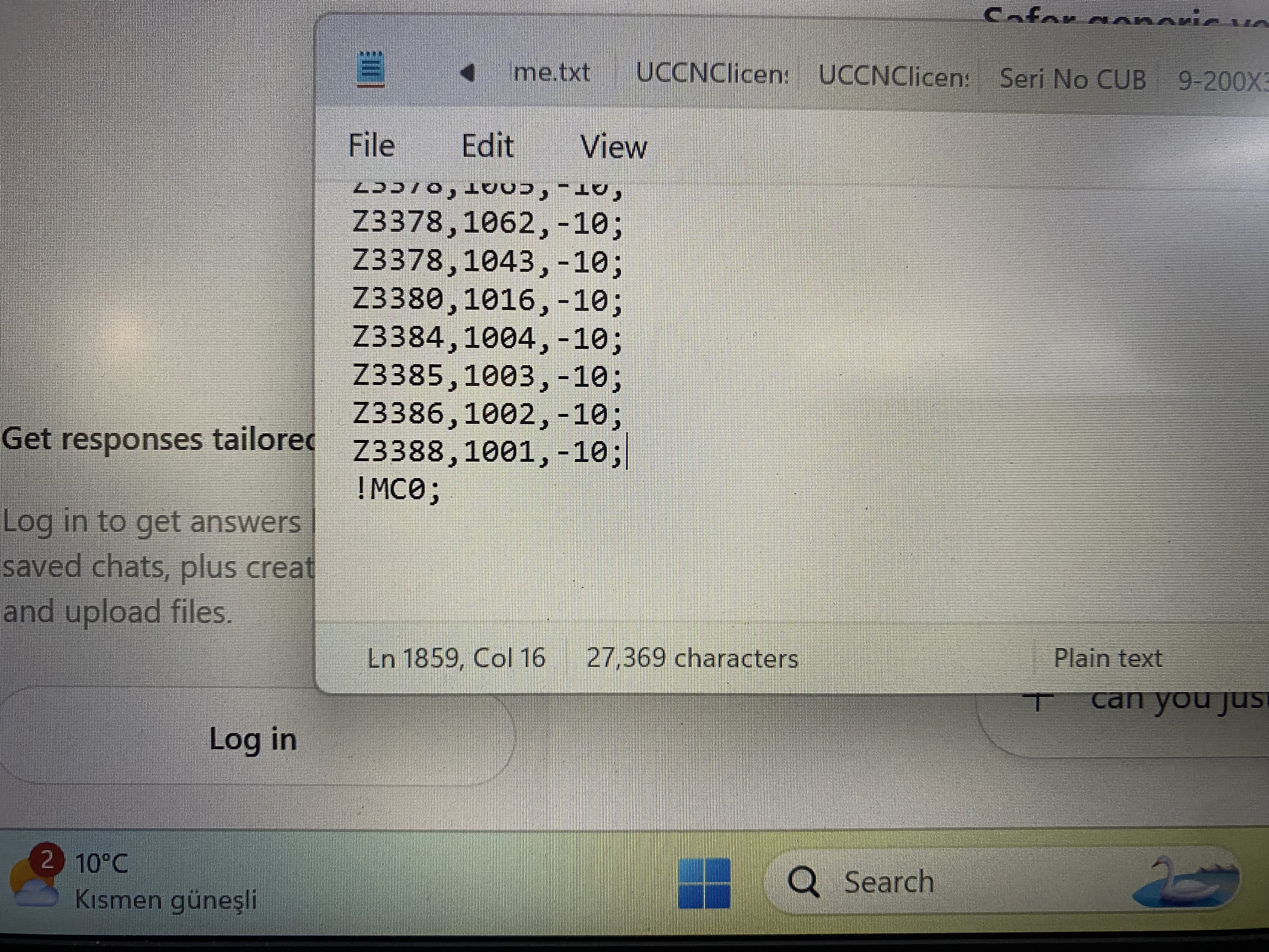
To generate machine instructions we used Mods, the Fab Lab CAM tool.
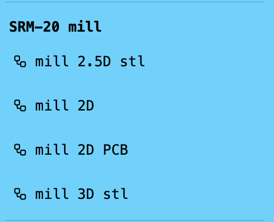
mill 2D pcb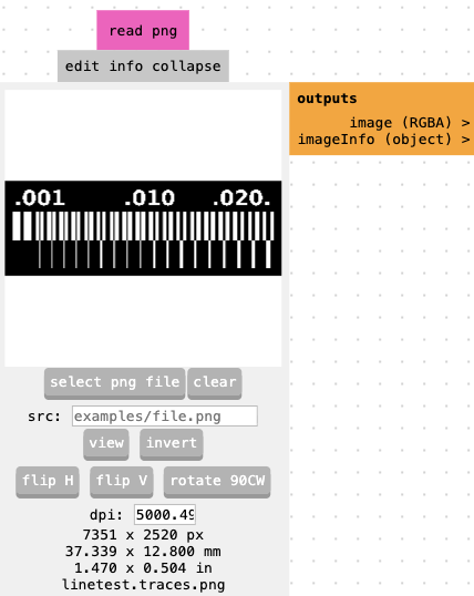
origin = (0,0,0)
Mods generates RML files for the Roland SRM-20.
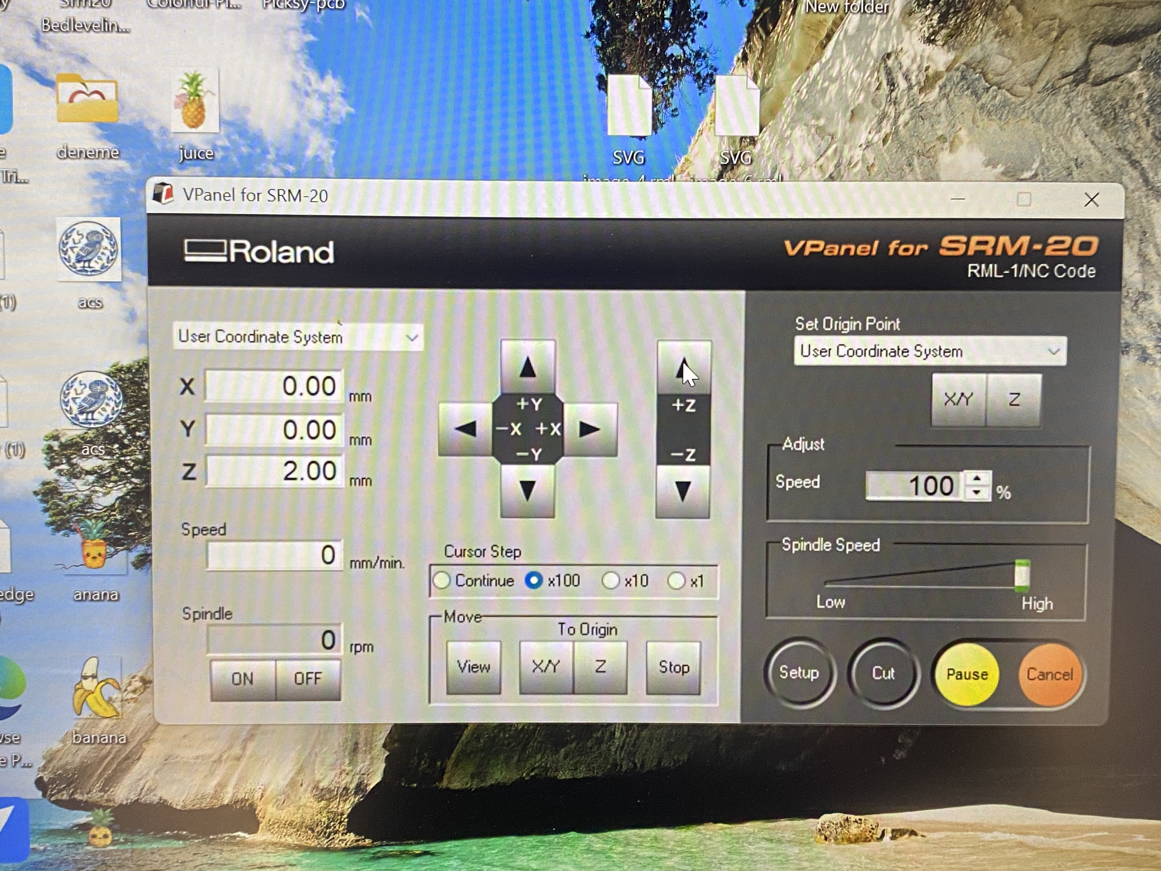
X = 0
Y = 0
Z = 0
Jog Height = 2 mm
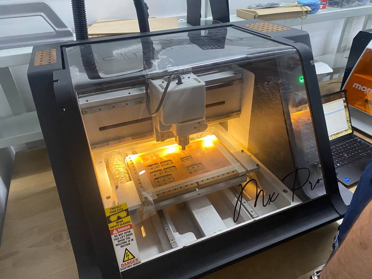
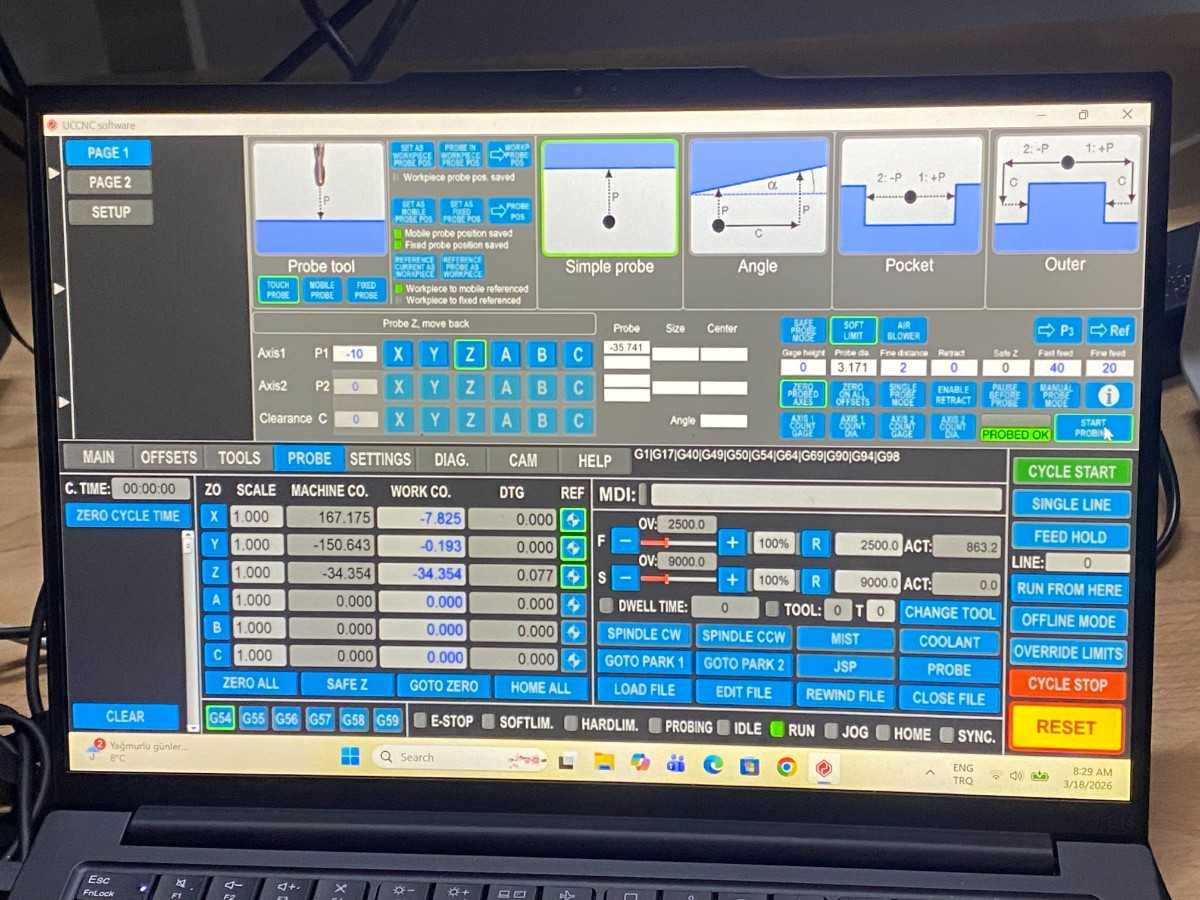
In addition to the Roland SRM-20, our lab also uses a Derinmotion Cube3D CNC milling machine for PCB fabrication.
This machine uses a different CAM workflow and accepts Gerber files directly.
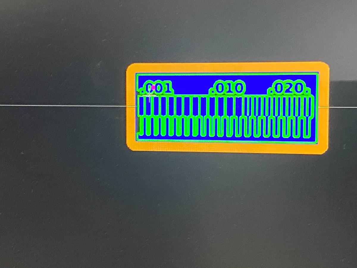
The Neil Gershenfeld trace test pattern was originally provided as PNG files.
Because the Cube3D software requires Gerber files, we converted the design using the following workflow:
PNG → SVG → KiCad → Gerber
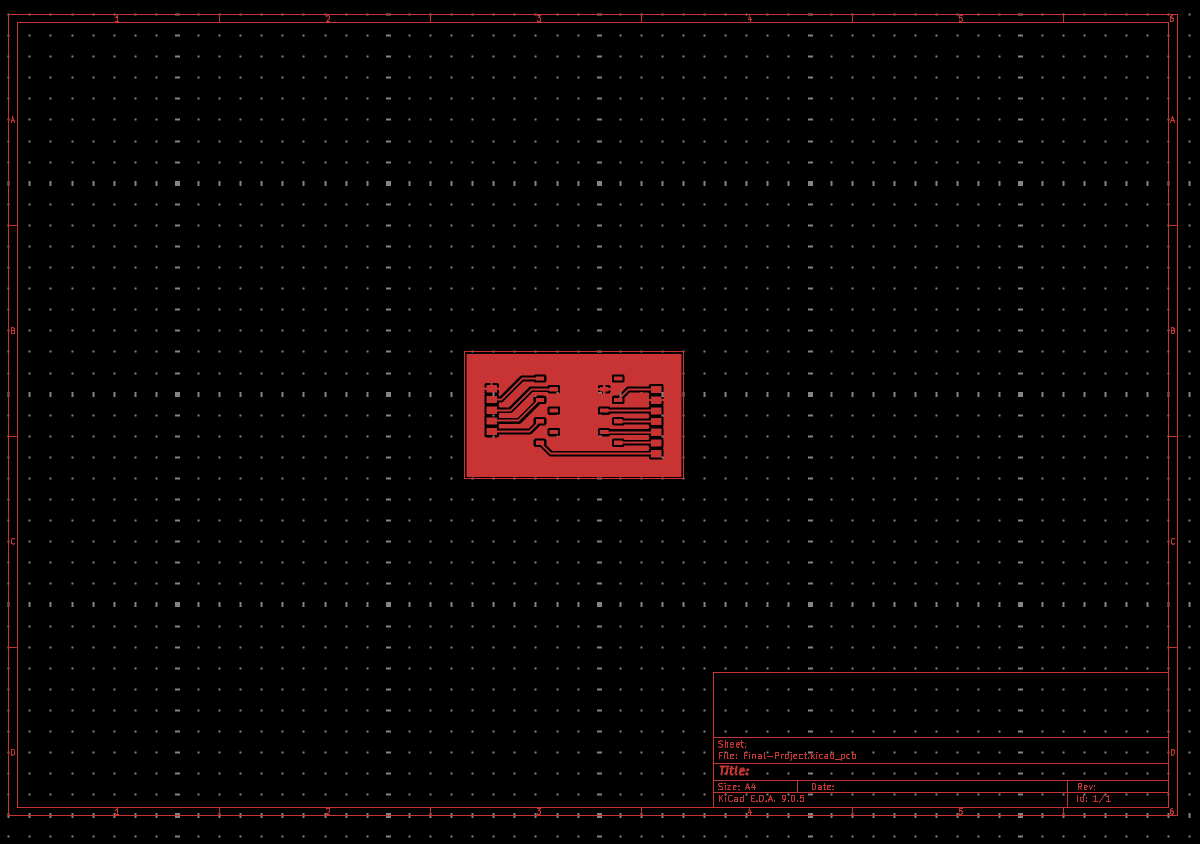
The PNG was converted to SVG, imported into KiCad, and exported as Gerber manufacturing files.
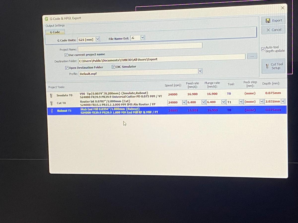
The Derinmotion machine is controlled using Cube3D CAM software.
The software requires a USB hardware key (dongle) to run.
After opening the software, the Gerber files were imported into the interface.
| Purpose | Tool |
|---|---|
| Trace milling | 0.2 mm engraving bit |
| Copper rubout | 1 mm tool |
| Edge cuts | 2 mm end mill |
Initially the spindle speed was set to:
24000 RPMThe spindle did not spin correctly at this speed.
After adjustment, the spindle speed was increased to:
40000 RPMAt this speed the machine operated correctly.
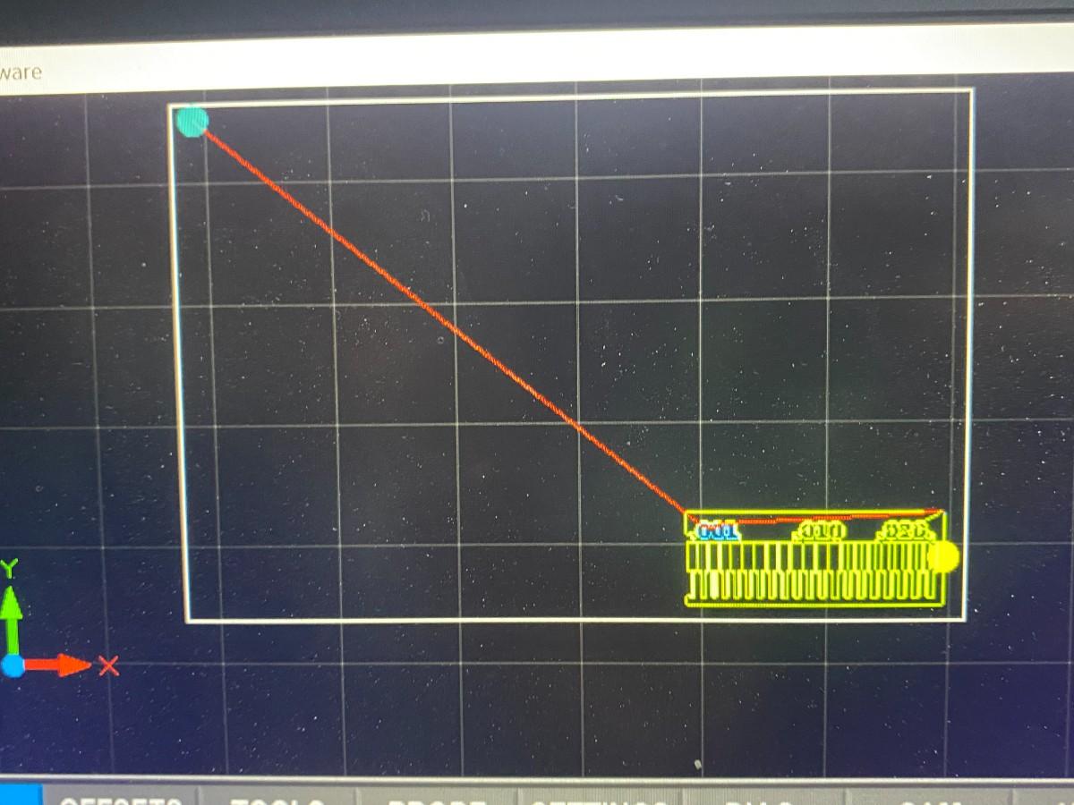
The CAM software generated four toolpaths:
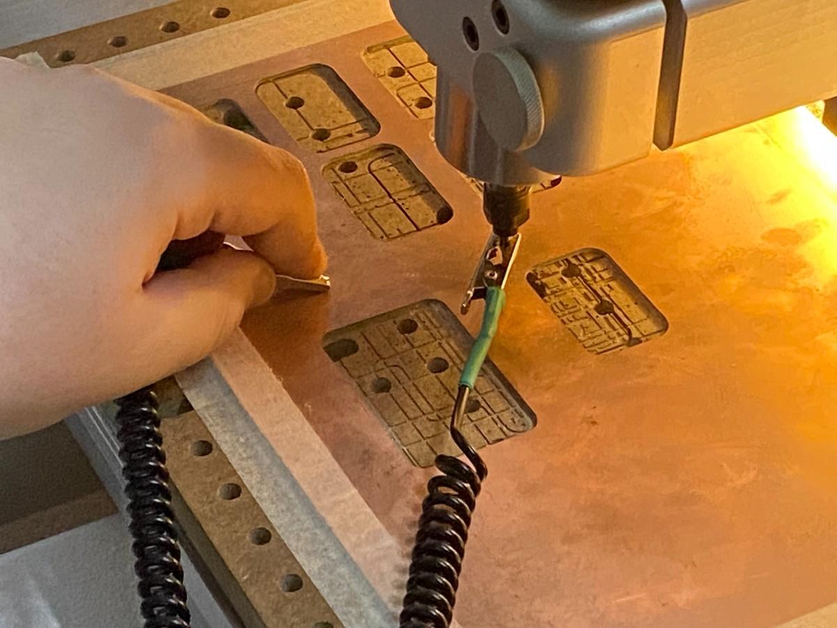
The machine automatically detects the copper surface to set the Z origin.
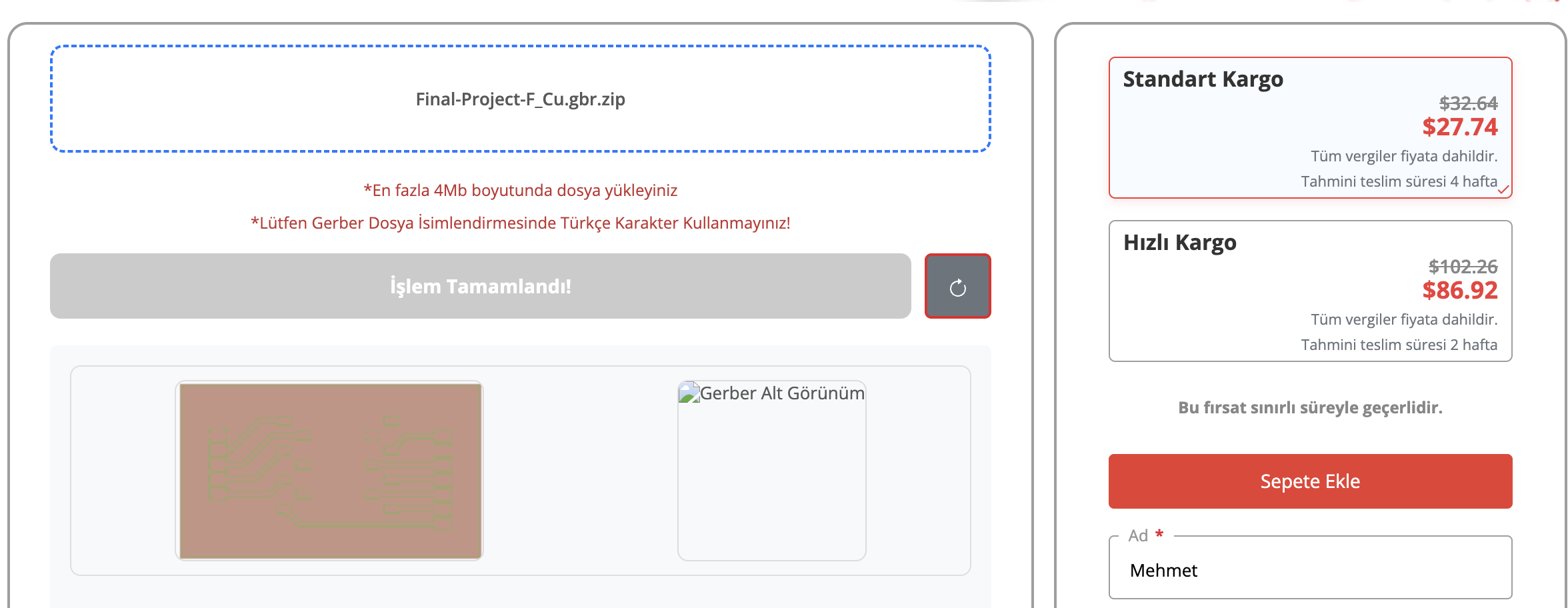
The second part of the assignment requires submitting a PCB design to a professional board house.
We selected PCBWay for fabrication.
Board house sent to is Robotistan PCB ordering.